Learning to fail and how you move on from it: In my previous two posts I had designed and created a pcb layout for a simple 555 timer flasher. I thought it would be a simple thing to do because I really wanted to test the workflow on how to create a pcb from start to finish.
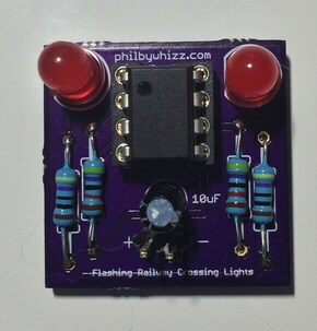
After placing and soldering all the components on my pcb, and applying power to it, I expected to see some nice flashing lights just like my breadboard model was doing. The first LED blinked on and off, the second blinked on.. and stayed on… Strange.
I double checked that the pcb matched the schematic – yep that is all correct. I turned on the circuit on the breadboard (I still have it on the breadboard as a working circuit when I created it) – and that was working. What could the problem be?
When showing off my excitement of designing my first pcb to an electrical engineering forum (EEVBlog) a kind soul (Hero999) pointed out that there was an error on my original schematic and that my circuit would not work.
After analyzing it a bit further I had come to the conclusion that I had failed to copy my breadboard layout to a schematic correctly. Because this was wrong, everything else was wrong. During this time I also must have altered the breadboard circuit without updating the schematic file.
My original breadboard circuit was based on the one here and you can clearly see my schematic doesn’t follow this (R2 connects to +V instead of pin3).
Doh!
Learning to Fail
So what have I learnt from all this?
I was so worried about creating a perfect schematic -> pcb workflow that I didn’t spend enough time on the breadboard -> schematic step causing everything to fail.
So while I did fail – I also succeed as the pcb is a correct representation of the schematic – just that the schematic was all wrong.
I also need to pay more attention to ALL the steps in the workflow and not just focus on one step. Each step is important and can have a cascading effect if you get it wrong.
All is not lost though – the same kind soul on EEVBlog (Hero999) has also suggested that I can fix it by removing a solder joint and running a manual wire to the correct location. I’m going to give that a go the next time I’m doing some soldering.