It’s been a while since I last posted an update on the Whizz80 computer. I’ve been a bit slack in documenting my progress because each time I move a little step closer and it is more fun to keep building and designing rather than writing up documentation. However I have reached a bit of a milestone with a simple, yet working system so now is the time to pause and take note on what I’ve done so far.
Here is the current photo of the breadboard in all it’s ugly glory. For a close up view simply click the photo below:
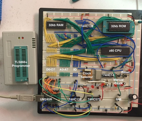
I’ve labelled some key areas of note on the image but here are some descriptions of some of the sections that I have so far:
- The top row contains 32kB RAM memory, logic for memory/io switching and the 32kB EEPROM. The EEPROM is in a ZIF socket for ease of removal to program via my TLS86+ programmer.
- The second row contains the system bus wiring and the z80 CPU.
- The third row contains the 3 different clocks with a selector switch (1Mhz, 2hz, Manual), A manual clock switch and Reset switch
- The fourth row contains a UM245R module, some extra ICs to help with the register selection and latching of the UM245R device. I also have a NMI trigger switch that I use to resume the CPU from a HALT operation (makes a nice handy hardware breakpoint).
The colors of the wires are important and mean something (although ignore the colors in the bottom row around the UM245R as I am using temporary connections).
- Red: +5v
- Black: Ground
- Yellow: Data bus lines
- Green: Address bus lines
- Blue: Control bus lines
- White: Misc signals
I’ve also written my first real z80 assembly code to test out the current system by reading input from the UM245R and outputting it back to the UM245R. So what ever you type on the terminal gets echoed back to you on the terminal. It makes a nice loopback test. You can find this source code up in the project github repository. I’ve tagged the source ‘loopback’.
The next steps that I need to do is to document some of the circuitry up on the main website and then create a more permanent circuit on prototype board.